 03. June 2026, 09:19 o'Clock
Article: The ABCs of Freight Transport: Interlocking Part 2 – Technical Development and Digital Control
Part 2 explains how signal boxes have evolved from mechanical lever systems to modern digital systems and what advantages this brings.
In Part 1, we explained how signal boxes secure routes, monitor tracks and guide trains without conflicts. Part 2 now examines how the technology behind this has developed – from the first mechanical systems to networked, digital interlockings.
Mechanical signal boxes – the beginnings
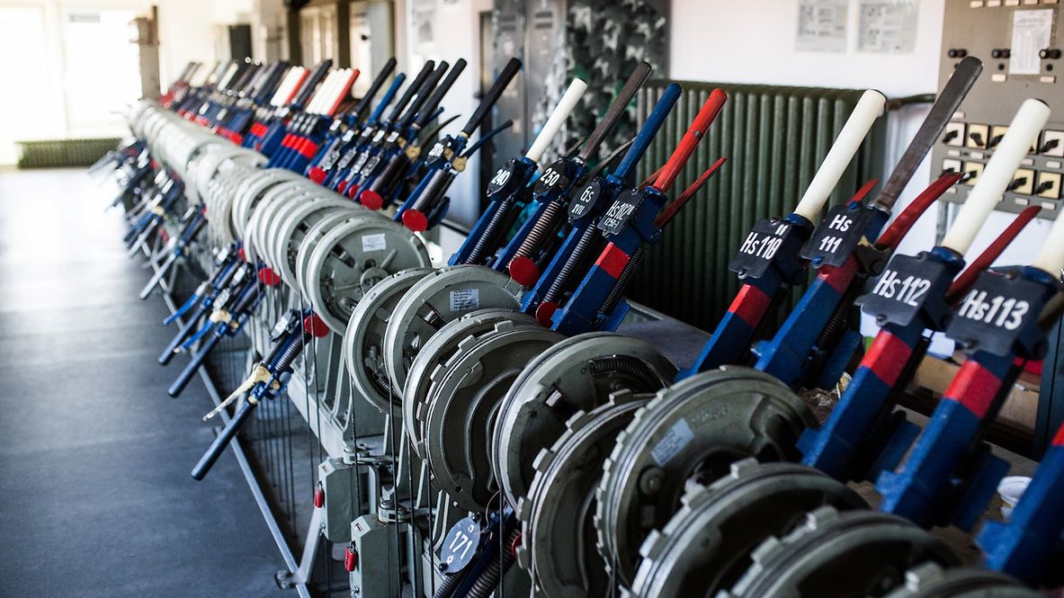
Earlier signal boxes operated purely mechanically: points and signals were operated directly via levers and cable pulls, and track clearance often still had to be checked locally by visual inspection. The control area was small and the operational effort high, which is why mechanical signal boxes are particularly suitable for simple control points with few points and a low number of trains.
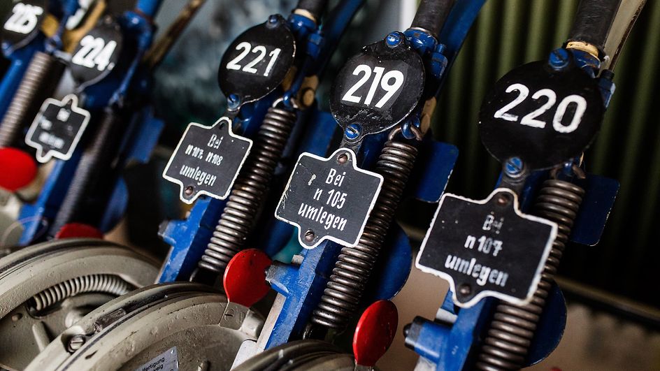
Route setting panel of a relay interlocking for monitoring and controlling complex railway station systems.
Electromechanical signal boxes – the first automation
Electromechanical systems combine mechanical operation with electric drives. Light panels or displays show the status of points and signals, and depending on the design, technical aids for track clearance may be available. Simple electrical interlocks prevent incorrect operation, enable larger control areas and reduce typical manual operating errors.
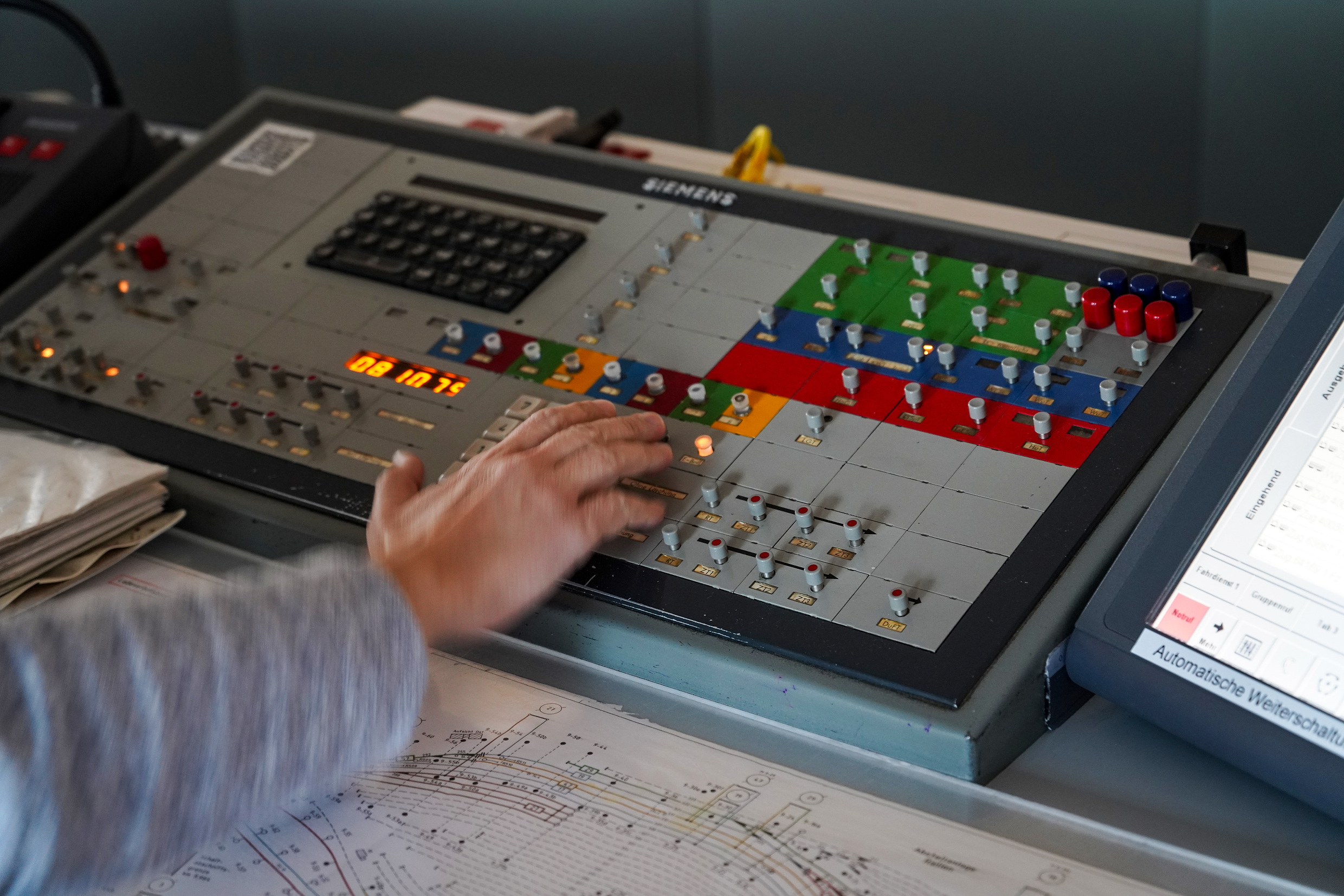
Operating table with buttons and signalling fields for controlling points and routes based on electromechanical relay technology.
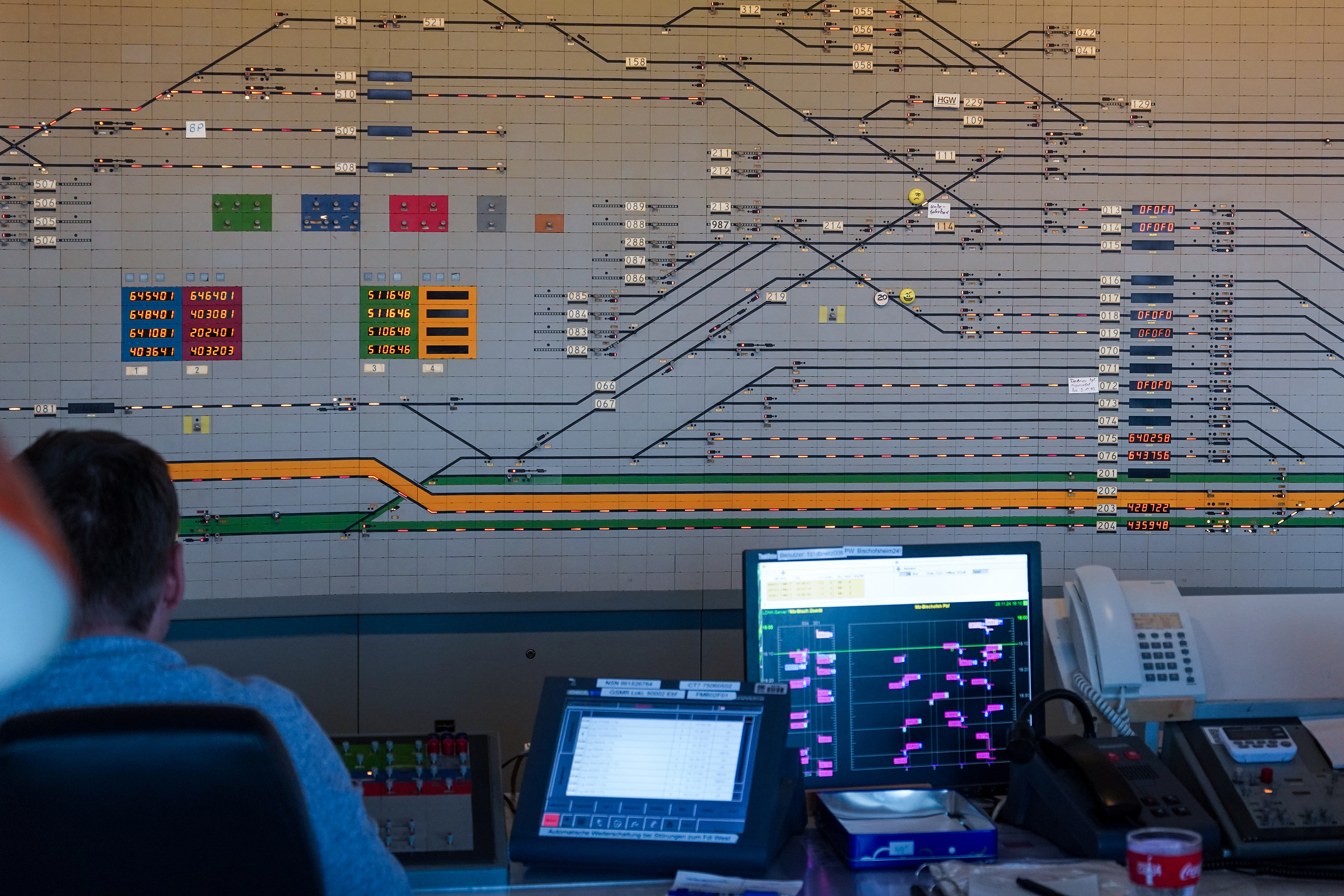
Relay interlocking – electrical logic for larger stations
Relay interlockings use hard-wired electrical logic. Routes are formed automatically, and track clearance and exclusion logic operate largely without manual intervention. Schematic route setting panels provide an overview of the track status and continue to make relay technology a tried-and-tested solution for medium-sized and large stations with dense train traffic.
Electronic interlockings (ESTW) – centrally controlled and networked
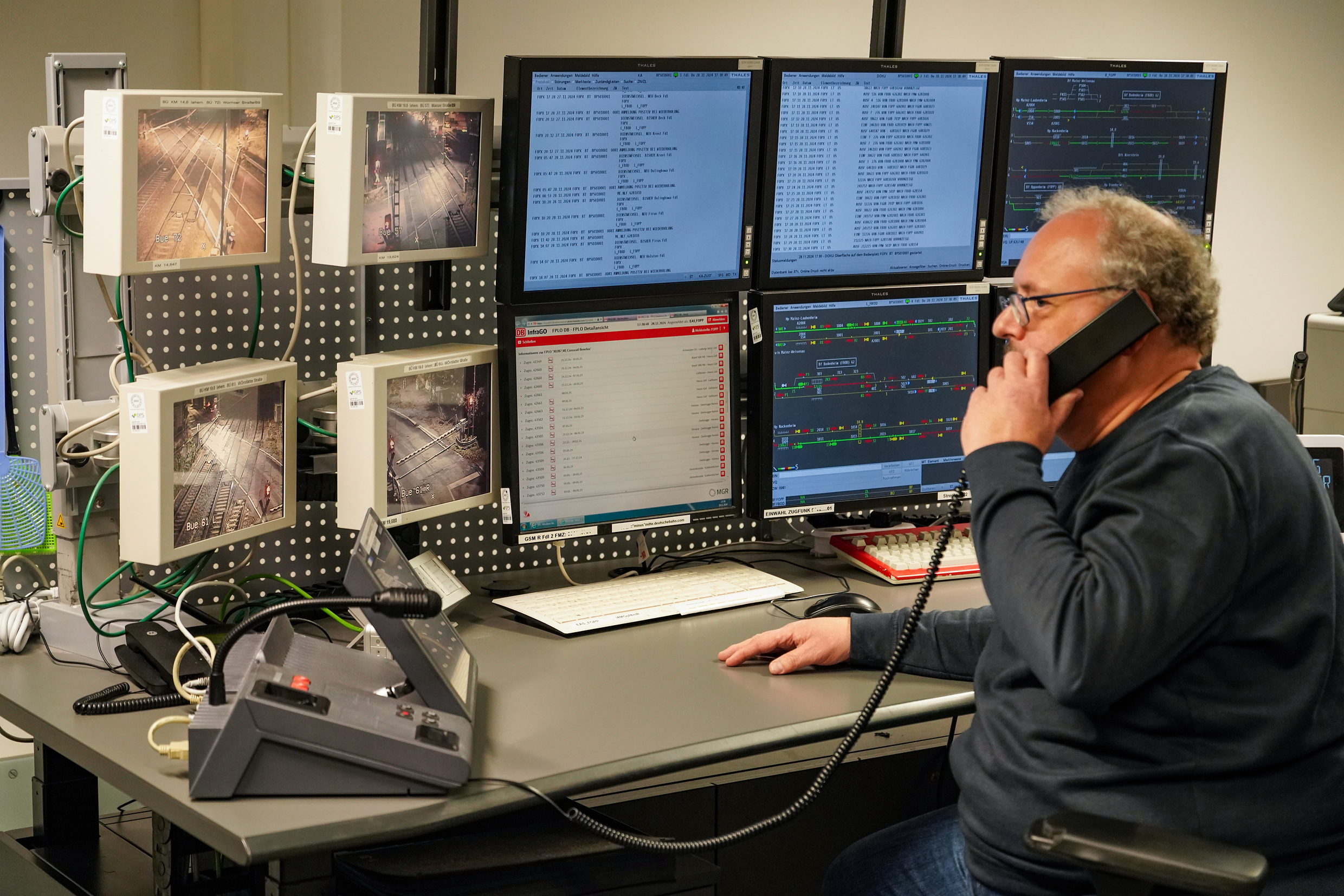
Central control system in the ESTW: Monitor workstation for operating large control areas with computerised safety logic and integrated remote monitoring.
In electronic interlockings, safety computers take over the role previously performed by relay logic. Multiple operator stations allow for the central control of large control areas; outdoor equipment such as points and signals are connected via modules, and status data can be read remotely. This facilitates the centralised operation of spatially distributed systems and supports faster fault diagnosis and troubleshooting.
Digital interlocking (DSTW) – IP-based and scalable
Digital interlockings operate with IP-based, distributed systems. Digital object controllers control points, signals and level crossings via secure networks. Expansions can be implemented with minimal intervention in the safety-critical logic. This makes digital interlockings particularly suitable for complex network sections where scalability and digital networking are crucial, and they form the basis for automation and – in combination with ETCS – standardised, interoperable interfaces in corridor traffic.
Modern functions in operation
This means that even heavily used junctions can be operated efficiently and safely.
- Routes are only authorised when all safety conditions are met.
- Track clearance is confirmed automatically (axle counters/track circuits) or via local control, depending on the signal box type.
- Flank protection is an integral part of route protection and is automatically interlocked.
- Status data enables remote monitoring, remote diagnosis and planned maintenance.
This means that even heavily used junctions can be operated efficiently and safely.
Signal box development follows a clear trajectory: higher levels of automation, larger control areas, centralised control and digital networking. Operators benefit from efficient processes, robust safety logic, faster fault clearance and the foundation for future automation. Modern ESTW and digital interlocking systems support capacity increases, particularly in conjunction with ETCS and digital signalling and safety technology.
 Go
Go